Led Light Emitting Diode clip art 116138 Free SVG Download 4 Vector Circuit Diagram I = LED current (we had been using 20 mA in our other calculations but since wiring LEDs in parallel draws more current I had to multiply the current that one LED draws by the total number of LEDs I was using. 20 mA x 2 = 40 mA, or .04A. And my values for the formula this time were: R = (9V - 1.7V) / .04A
Learn how to power a light-emitting diode (LED) with a series resistor, a constant current source, or a switched-mode power supply. Find formulas, examples, and diagrams for different LED drivers and applications.

Easy LED Circuit : 5 Steps (with Pictures) Circuit Diagram
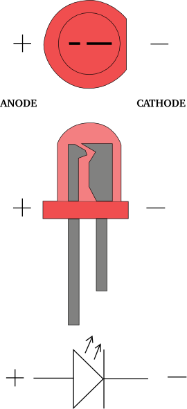
Learn what a LED schematic diagram is and how to read it. Find out the basic structure, advantages, and applications of LEDs, and the components needed to connect them to a circuit.

Learn the basics of LED circuit diagrams and how to create a basic LED circuit with a few components. Follow the step-by-step guide and experiment with different resistor values to adjust the brightness of the LED.
Wiring LEDs Correctly: Series & Parallel Circuits Explained! Circuit Diagram
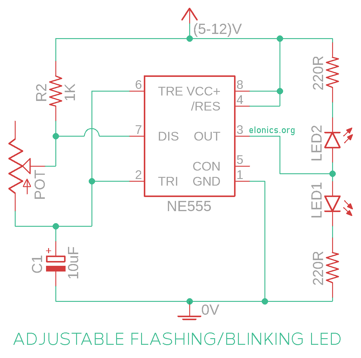
Here is a diagram of the basic circuit. Just as before, the LED positive side is connected to the battery's positive side, and likewise negative to negative. The current will flow from the battery through the resistor and LED and then back to the battery. The resistor and LED are connected in series, which means one after the other.
