Figure 1 from Design and implementation of High Performance Voltage Circuit Diagram An oscillator is an electronic circuit which generates a repetitive, or periodic, time-varying signal. In the context of MCU Series 1 or Wireless SoC Series 1 devices, this oscillator signal is used to clock execution of instructions and peripherals in the device.

Osc illator Design Introduction What makes an osc illator? Types of oscillators Fixed frequency or voltage controlled osc illator LC resonator Ring Oscillator Crystal resonator

How to Make Pierce Oscillator Circuits Circuit Diagram
An Oscillator is basically an Amplifier with "Positive Feedback", or regenerative feedback (in-phase) and one of the many problems in electronic circuit design is stopping amplifiers from oscillating while trying to get oscillators to oscillate.

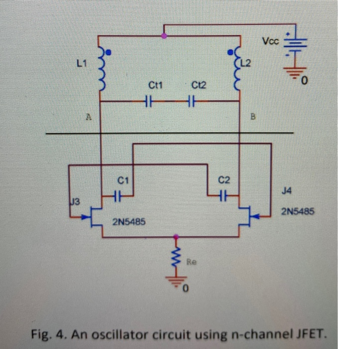
The high input impedance and high gain of the FET encourage ease and efficiency in multiple transistorized oscillator circuits. often, the FET can be utilised directly in transistor circuits and needs no unique circuit components. This convenience is vital, particularly in crystal-controlled, RC-tuned, and capacitance-feedback oscillators. 2-port negative resistance circuit can now simply be terminated in the opposite sign reactance to complete the oscillator circuit. Alternatively high-Q series or parallel resonator circuits can be used to generate higher quality and therefore lower phase noise oscillators. Over the years several RF oscillator configurations have become standard.

PDF AN0016.1: Oscillator Design Considerations Circuit Diagram
Figure 2 shows a Pierce Oscillator design commonly used in digital processor designs. In this type of crystal oscillator design, the filter consists of the crystal's equivalent model and the external load capacitors. The exact frequency at which an oscillator will operate is dependent on the loop phase angle shifts within the oscillator circuit.
Explore the fundamentals of Current Controlled Oscillators (CCOs), their working principle, types, applications, design considerations, and more. Introduction to Current Controlled Oscillators A Current Controlled Oscillator (CCO) is an essential component in many electronics applications. It is an oscillator device whose frequency is controlled by an input current. The output frequency of a
